Donkey Kong, DK Junior, DK3, Mario Bros., Popeye, etc. all use inverted video with unamplified audio. What this means is that when the game board itself outputs color data to the monitor, it's outputting inverted colors, like a photo negative. Black is white, white is black, etc. The audio is unamplified on the board, meaning the audio data is essentially "silent" until it reaches a dedicated amplifier somewhere else, which then amplifies the audio (and allows you to adjust the volume, etc.) The reason for this is because Nintendo arcade machines used monitors produced by Sanyo and Sharp which required these strange specifications- a dedicated circuit board on the monitor itself re-inverts the colors to correct them and amplifies the audio. Keep in mind also that these Sanyo monitors actually support regular video but were seemingly modified to only support inverted colors like the Nintendo boards produce, so it's kind of a chicken-or-the-egg scenario. Did Nintendo request this strange limitation? Did Sanyo require it? Who knows. Sanyo monitors can be modded to support standard colors by repopulating missing components on the monitor chassis, which, likewise, is the story for the Nintendo boards themselves.
In the case of our DK Junior board, all of the necessary circuitry to "correct" the colors and amplify the audio exist on the board itself but are completely unpopulated. This, combined with the open availability of the schematics (required by game operators to fix the boards), means bootleggers typically just cloned the original hardware outright and populated those empty spots to allow bootleg DK Jr. boards to run in non-Nintendo cabinets. Easy.
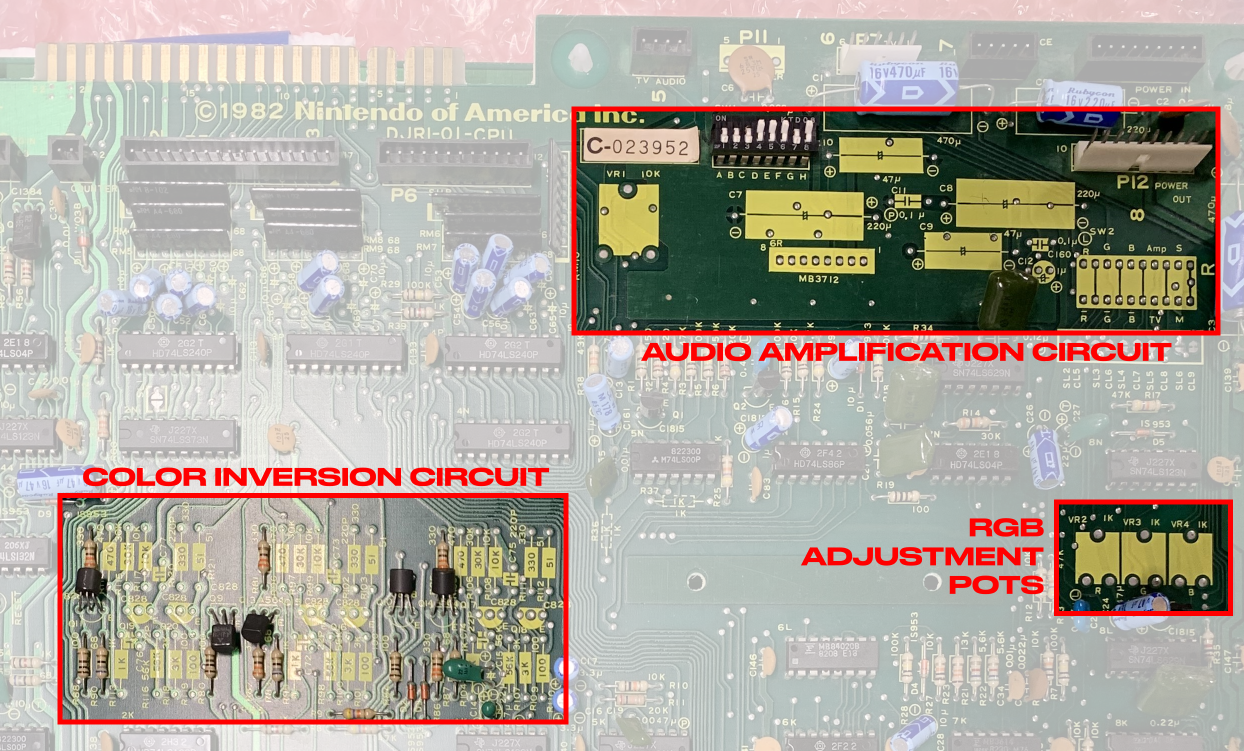
The mission with this mod was to repopulate the missing components on a legitimate Nintendo DK Junior board to allow for "corrected" colors and amplified audio, alongside the ability to flip the screen image up and down (required based on the orientation of some monitors). Thanks to an unpopulated 10-position dip switch location on the board (in the bottom right of the audio amp circuit above), these circuits can be toggled on and off, meaning the board itself is now "cross-compatible" with both original Nintendo cabinets and standardized Jamma-style cabinets.
Why You Should or Should Not Do This
Why you should do this:
- Because you enjoy it.
Why you should not do this:
- Because cheaper, easier, more cost-effective alternatives exist and have existed for decades.
This project requires a lot of time, money, and energy to complete (not to mention prior experience and appropriate tools) and for approximately $70 you can buy a plug-and-play Jamma adapter from ebay and accomplish literally the same thing instantly, not to mention that that Jamma adapter can then be used on multiple Nintendo boards, meaning you can plug and unplug this "expanded functionality" into any Nintendo game of your choosing instead of dedicating the time needed to just strictly modifying Donkey Kong or Donkey Kong Junior.
So why am I doing this? Because I'm a wackjob and I risk my investments, that's why. It'd be less embarrassing to tell my family I was just a gambling addict instead. I'd probably save more money that way, too.
The Mods and What You Need
The following is a list of parts that you'll need to populate each unused circuit on the board.
The Color Inversion Circuit
Thankfully there's a handy writeup from 1998 on Mike's Arcade explaining the color inversion mod. Credit to Joel Rosenzweig and Dick Millikan for their work on this document. I'm going to share the same parts list here as described in that document (swapping out just the transistor):
  Resistors:
Part    Quantity        Location
1K      5               R113, R95, R104, R36, R37
56K     3               R116, R98, R107
3K      3               R118, R100, R109
100*    3               R119, R101, R110
470*    3               R114, R96, R105
30K     3               R115, R97, R106
10K     3               R117, R99, R108
330*    3               R120, R102, R111
51*     3               R121, R103, R112

*NOTE, these values are not K Ohm.  They are not typos.
All resistors are 1/8 watt.


Variable Resistors (POTS)
Part    Quantity        Location
1K      3               VR2, VR3, VR4

Transistors
Part    Quantity        Location
2SC1815  6       Q15, Q16, Q17, Q18, Q19, Q20 **

Capacitors
Part    Quantity        Location
220pf   3               C73, C75, C77
22pf    3               C72, C74, C76
The document mentions taking caution with the transistors due to the unusual lead order. Another writeup from Aussie Arcade by Kaizen explaining these mods elaborates that the transistor used should be a 2SC1815 (as opposed to the suggested 2N3904 replacement mentioned in the Mike's Arcade document), and although it seems like both aforementioned technicians had trouble finding these transistors I was able to pick up several for relatively cheap on Mouser.
The resistors I used were 1/8W metal film resistors from Tayda Electronics in Thailand. The leads on these are very thin and bendy but the resistors themselves are cheaper than dirt and based on tests online are alarmingly functional given the cost. Likewise, you can pick up the two types of required ceramic disc capacitors here (for 220pf) and here for (22pf).
I used the following variable resistors from Mouser for the RGB adjustment pots. These are 1Kohm 10mm potentiometers.
Once you've got your parts together the procedure is straightforward. Using a soldering iron apply small dabs of solder to each unused via. Take your desoldering gun and carefully suck out the solder inside of each via, giving you empty holes to plug your new components into. Install and solder them all in, perform any clipping and cleanup necessary, and you're done.
The Audio Amplification Circuit
The Aussie Arcade post linked above goes into detail about this but I'll give the basic rundown. The following parts are needed for this circuit:
Capacitors
Part        Quantity    Type                      Location
220uf 16v   2           Axial Electrolytic        C7, C8
47uf 16v    2           Axial Electrolytic        C9, C10
0.1uf 50v   1           Radial Polyester          C11
1uf 50v     1           Radial Electrolytic       C12
0.1uf 50v   1           Radial Ceramic            C160

Other
MB3712      1           Audio Amplifier           6R
10k 15mm VR 1           Variable Resistor         VR1
Remember, you can substitute capacitors with caps of a higher voltage rating as long as the capacitance is the same. I used 25v caps in place of 16v on my board. This is the variable resistor I used with the accompanying shaft. This gives us an on-board volume knob!
Like the color inversion circuit process it's largely the same- apply solder to the unused vias, desolder and clear them out, then install your components. Solder them in, clip and cleanup, done.
Our New Handy-Dandy 10-Position Dip Switch
Last but not least, it's time to install our new dip switch bank that allows us to toggle our new circuits on and off. We need a specific size of 10-position dip switch for this board... so here's a link to exactly what you need. By now you should know the drill. Ready the unused holes and solder in your new dip switch bank.

THE MISTAKES
This was not my first rodeo with soldering but it's one of the more extensive solder projects I've done to-date so lemme just emphasize and highlight some very important tips to prevent any future fuckups on either my behalf or yours (if you, as the reader, have any interest in soldering).
Mistake #1: Lifting Pads
This is one of the most dreaded things that can happen when soldering and it occurs primarily when desoldering components. All of the holes on a circuit board are called Vias, and the little conductive rings surrounding each via are called Pads. Your solder adheres to these pads to provide a solid connection with whatever traces or planes these vias are connected to. Without pads your solder won't really stick, and it'll stay globbed up and mangled on the tip of whatever component leg you're trying to solder. It's actually kind of alarming how poorly it all comes together when there's no pad to help you out.
Lifting a pad is when one of these little shiny rings literally lifts up off of the board while soldering. At that point, provided it's too far gone and has left the board, it's over for that pad. You're now stuck trying to figure out a new, creative way to remedy this problem and reconnect the now-broken trace without it looking like the ugliest shit in the world (which it unfortunately probably will, since nothing looks nicer than a clean solder joint and no amount of bodge wire creativity can replace that).
While working on this board I had one single via/pad that was giving me a hard time when attempting to desolder it- the primary reason was that it was directly connected to a giant ground plane, so it required some extra heat to get any action going with it. This is where the solution lies, but I struggled to realize that in the moment and accidentally removed roughly a quarter of the pad. Thankfully the rest of the pad remained, but now we have this awkward ovally half-circle looking shape underneath instead. I'm lucky the specific pad in question had plus-shaped traces running in all directions, so even if one of them was nicked the rest would still connect just fine, but any damage to any board is a step in the wrong direction.
So how do we avoid this in the future? Well, what we need to do is increase our heat on the desoldering gun in order to thoroughly heat all the solder in the via going through. This allows us to get it right the first time and suck out the solder we need removed without mucking with the pad too many times. There's a finite amount of times you can heat a pad before it lifts and this varies based on the board and how well it was manufactured, so getting things done right in as few steps as possible means heating the pad less and avoiding this whole fiasco. Keep in mind that increased heat can lift pads too if the board in question was built like junk, but for this specific instance where the solder inside the via wouldn't fully empty when sucked the increased heat was necessary and would have prevented the pad from being fucked.
There's a variety of ways to "correct" the broken pad but because it maintained connection in this case it wasn't really needed, and ironically I ended up using a different via entirely after I discovered the pad I damaged connected to the same ground plane as several other nearby vias. Using one of these alternate vias allowed me to swap out my axial capacitor for a much cheaper, higher quality radial one. Mistakes Into Miraclez... Lol!! Either way I ran a short bodge wire from the damaged pad to the alternate pad I used just for peace of mind and to "fix" the damaged pad so it looks much cleaner than just leaving the pad busted.
Mistake #2: "I can do this cheaper myself"
No I can't. At first I thought this would be an inexpensive alternative to buying a premade Jamma adapter but the reality is I repeatedly ordered the wrong parts, repeatedly forgot certain parts, and ultimately ended up spending probably double what I would've spent had I just bought the damn adapter.
Mistake #3: Axial Capacitors (and Why They're Annoying to Replace)
Axial capacitors are the horizontally-oriented caps (as opposed to radial caps, the vertical ones). Axials lay flat like little logs, or Twinkies, and are ultimately kind of outdated. They don't last as long as radials from what I've heard and if you can manage to find axials in the correct values you're after it'll no doubt be more expensive than just buying radials, not to mention a lot of the "top tier" cap manufacturers like Nichicon and Rubycon don't even make axials anymore, or if they do they're either NOS or otherwise impossible to find.
I went with Vishay caps for the axials on this board which proved problematic for the 220uf caps because the leads they use are slightly thicker than the original leads, or the leads you'd find on other caps like Nichicons. They fit but they fight to get in, and when desoldered it seems like the increased heat from the thicker leg potentially widens the via. It's a lose-lose situation, since it's technically damaging the board, altho it doesn't affect functionality and the damage itself is near-impossible to notice.
In some cases radial caps can be "converted" into axials by laying them sideways and bending the positive lead (the longer one) up and over the barrel of the cap, then bending it down into the correct via. Unfortunately this only applies to some caps as not all caps have leads long enough to reach each hole.